Real-time Slip Detection and Traction Control of Electrical Powered Wheelchairs
Hongwu Wang, MS, Benjamin Salatin, BS, Garrett G. Grindle, MS, Dan Ding, PhD and Rory A. Cooper PhD
Department of Rehabilitation Science and Technology, University of Pittsburgh
Human Engineering Research Laboratories, VA Pittsburgh Healthcare System
ABSTRACT
The purpose of this study was to develop an electrical powered wheelchair (EPW) control system with the ability to detect and compensate for wheel-slip in real-time. A smart EPW platform was designed and built with a real-time computerized controller that records wheel speeds as a means to detect slip. The slip coefficient was defined by the difference in the rotational velocity of the caster and driven wheel. To evaluate a simple wheel slip controller, our EPW was driven over five different surfaces at three speeds. Paired t-tests showed that with anti-slip control, there was significant (p<0.001) lower slip coefficient than without anti-slip control. Experimental results showed that the performance of anti-slip control was consistent on the varying surfaces at different speeds.
KEYWORDS:
Electric-powered Wheelchairs, slip detection, slip coefficient, traction control
BACKGROUND
Wheelchair control methods are important to safety and performance. However, wheelchair users usually have difficulty on ice, slippery surfaces and soft ground [1]. Wheelchair tires even though provided with special tread patterns may slip on slippery or icy surfaces. It is not unusual during cold weather for a wheelchair to become immobilized due to spinning of the drive wheels. The user may thereby be subjected to unnecessary exposure to cold as a result of the inability of the wheelchair to move. Ding and Cooper published a review of current technology and provided insight into future directions for EPW, in which traction control were noted to be important with increasing outdoor use of EPW [2]. By implementing traction control on an EPW, the driving environment may be expanded and driving safety improved. However, little research has addressed enhancing traction of an EPW under sub-optimal surface conditions. Work related to traction control is usually found in the literature on automobiles [3, 4].
Cooper proposed that during speed control of EPW, several simplifying assumptions are made when modeling the wheelchair. For example, on a side slope only the vertical forces that act on the front castors are included, the front wheels are assumed to be loaded equally, the center of mass is modeled as stationary with respect to the chair, the wheels do not slip, and changes in slope are gradual [5]. However, EPW wheel slip frequently occurs when driving over low-traction terrain, deformable terrain, steep hills, or during collisions with obstacles, and can frequently result in wheelchair immobilization. Thus, the wheelchair should be able to detect the slip when it is on such surfaces and feed information to an advanced speed controller.
The goal of this research is to investigate possible control solutions for EPW to be able to detect wheel slip and eventually maximize traction. The controller developed and tested for this study is based on the Versalogic EBX-12 COBRA industrial single board computer installed with VxWorks 6.3 real time operating system that replaces the Original Equipment Manufacturer (OEM) control electronics on an EPW as well as wheel encoders and inertia sensors to provide the researcher with control of the driving algorithms and the ability to read state data. The system is semiautonomous, which takes advantage of the intelligence of the wheelchair user by allowing the user to plan the general route while taking over lower level functions such as slip detection and anti-slip control [6].
Research Questions:
- To determine whether the developed controller could be able to detect wheel slip?
- To determine whether the proposed controller could provide improve control of traction?
METHODOLOGY
Rationales
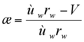
The wheel slip of a mobile robot can be detected by comparing wheel velocities to the robot body velocity. Experimental results show that the algorithm can quickly and accurately detect immobilization in various scenarios [7]. The wheel slip x is usually defined by a nonlinear function of the wheel velocity wW and the wheelchair velocity V shown in equation 1. The wheel slip x can be monitored via the equation 1, which also functions as a threshold when real time traction control algorithms are implemented. The anti-slip control algorithm compares the speeds of the driving wheels and the caster. The caster wheels are not powered, and therefore caster speed provides an estimate of the EPW velocity. Loss of traction, wheel slip, was defined as a difference in the angular velocity of each drive wheel with respect to the caster of greater than 20%. When loss of traction was detected, the driving wheel speed was decreased until the wheel slip was within tolerances, and the EPW continued forward progress albeit possibly at a reduced speed.
Equation 1:
Test Wheelchair
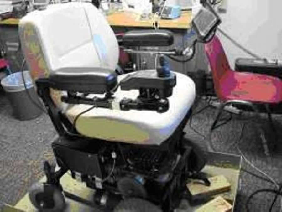
Figure 1. (Click for larger view)
The controller hardware and sensors were mounted on a Golden Alante wheelchair frame. The core electronic systems were divided into high and low power components. The high current components consist of two 12V batteries, two 420W motors with brakes, two industrial amplifiers, a brake release circuit, a DC-DC converter, and fuses. The motors and batteries are original equipment retained from the Golden Alante EPW that was chosen as the base. The Alante base was chosen for its simplicity and ability to operate as a front wheel or rear wheel drive EPW. The power amplifiers used were the Advance Motion Control 50A8DDE, which are power rated for 25A continuous and 50A for 2 seconds and accept a 20-28V input. The output for the 50A8DDE is controlled by a pulse-width-modulation (PWM) signal and a digital direction pin. The joystick was from the wheelchair OEM from which two voltage outputs representing speed (vertical axis) and direction (horizontal axis) and are within 1 V to 4 V ranges, with 3.5 V representing the neutral position voltage. The sensors on the EPW employed in this study were three digital incremental encoders attached to both of the driving wheel and one of the casters as well as a six degree of freedom Micro-Electro-Mechanical Systems (MEMS) based inertia sensor amounted on the seat post of the EPW (Fig. 1) which provides the linear acceleration and angular velocity of the EPW. The data collected were recorded at 200 HZ on an onboard 32 Gb solid state hard drive. Control algorithms were written in C language implemented on a VxWorks real-time Operating System.
Experimental Protocol
Figure 2. (Click for larger view)
The experimental protocol consisted of driving the EPW with and without the control algorithm in-turn on five difference surfaces which incorporated both indoor and outdoor environments (Fig. 2) and collecting data about the wheelchair speeds. A 2.44m Teflon sheet attached to an adjustable slope ramp with maximum 50 was used to simulate a slippery surface (e.g., ice, snow, wet grass). For each of the surfaces, in order to decrease the experimental error, the EPW was driven in the same manner for each trial. The control parameters were measured and recorded during each trial. The driving test was carried out using a step-response at three different desired speeds, fast 2 m/s, medium 1.5 m/s, and slow 1 m/s. All tests were conducted driving straight forwards, turns and reverse driving tests will require further development and are left for future studies. The order of testing the driving surfaces was randomly chosen; however, for each surface, the EPW was always driven with the fastest speed first, then medium and then slow speed. Also tests on the next surface were initiated after all the tests on the former surface were completed. The actual speeds of the two driving wheels and the caster were collected by encoders incorporated on the EPW. The caster encoder data were compared with the average of the driving wheel encoder data in the controller to detect the slip then initiate traction control if slip was detected.
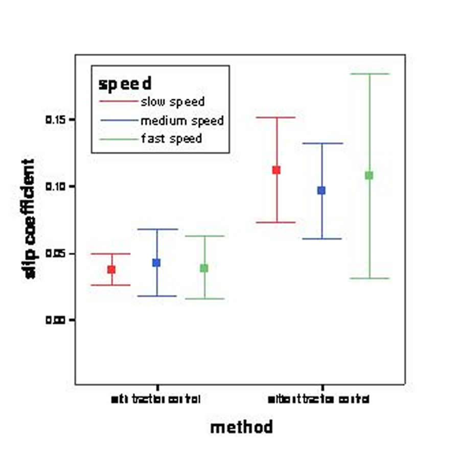
Figure 3. (Click for larger view)
In order to evaluate the performance of the control algorithm, slip coefficient, defined as difference between driving wheel speed and wheelchair speed (caster speed) normalized to the driving wheel speed was used to evaluate traction control.
Data Analysis
Data for each trial were analyzed using Matlab 7 (R14) and normalized to 10 seconds for comparison purposes. The difference of slip coefficient for the two methods was compared using the paired t-test. The alpha level was set at 0.05 apriori.
RESULTS
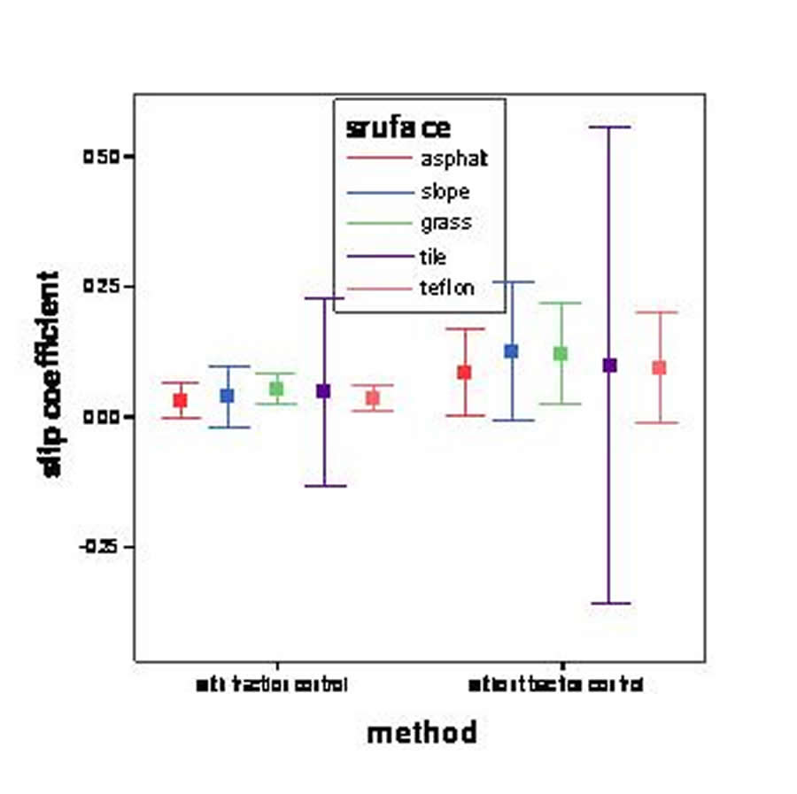
Figure 4. (Click for larger view)
The physical parameters for the test EPW system were measured (see Table 1). The mass parameter in the table includes the EPW and the test-pilot (146 lb). Table 2 shows that overall the traction control (0.04 + 0.02) had significantly decreased the slip-coefficient compared with open loop control (0.11 + 0.04). The slip-coefficient, with open-loop, the faster the speed, the bigger the slip coefficient indicating greater slip was detected. However, with traction control, the slip coefficient was visibly lower at all desired speeds (Fig.3). Similarly, with the traction control, lower slip coefficient was observed on all the five tested surfaces (Fig.4).
| Surface Variables | Teflon |
Tile |
Asphalt |
Slope |
Grass |
|---|---|---|---|---|---|
μ |
0.04 |
0.55 |
0.72 |
1.02 |
0.35 |
α |
30 |
30 |
10 |
110 |
00 |
β |
00 |
1.20 |
0.70 |
80 |
00 |
θ |
00 |
00 |
00 |
00 |
00 |
 (friction coefficient)*
Table 2. Slip coefficient of all the tests with and without traction control
| method | Slip Coefficient (Mean + Std) | P |
|---|---|---|
with traction control |
0.04+0.02 |
P<0.001 |
without traction control |
0.11+0.04 |
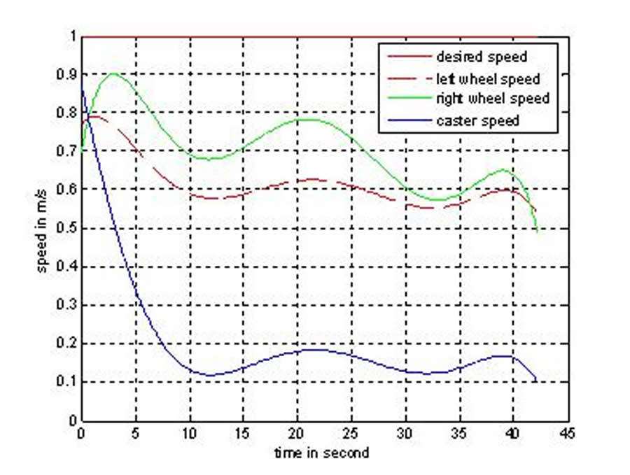
Figure 5. (Click for larger view)
During the experimental tests, no slip could be seen by the investigators while observing the tests. In order to test whether the anti-slip control method was effective, we put the Teflon on a ramp with 50 degrees slope on which the wheelchair was driven. The Fig. 5 and Fig. 6 show how the wheelchair performed during this scenario. From figure 5 we observed that with open-loop, when slip happened, the two driving wheels kept spinning while the speed of the EPW was almost zero. In figure 6, we could observe and recorded that the controller decreased the driving wheel speed in order to gain traction. However, Teflon surface length was insufficient to have the EPW fully reject slip, and regain the desired speed. Anti-slip control is an area where further work is needed to overcome slip more rapidly and effectively.
DISCUSSION
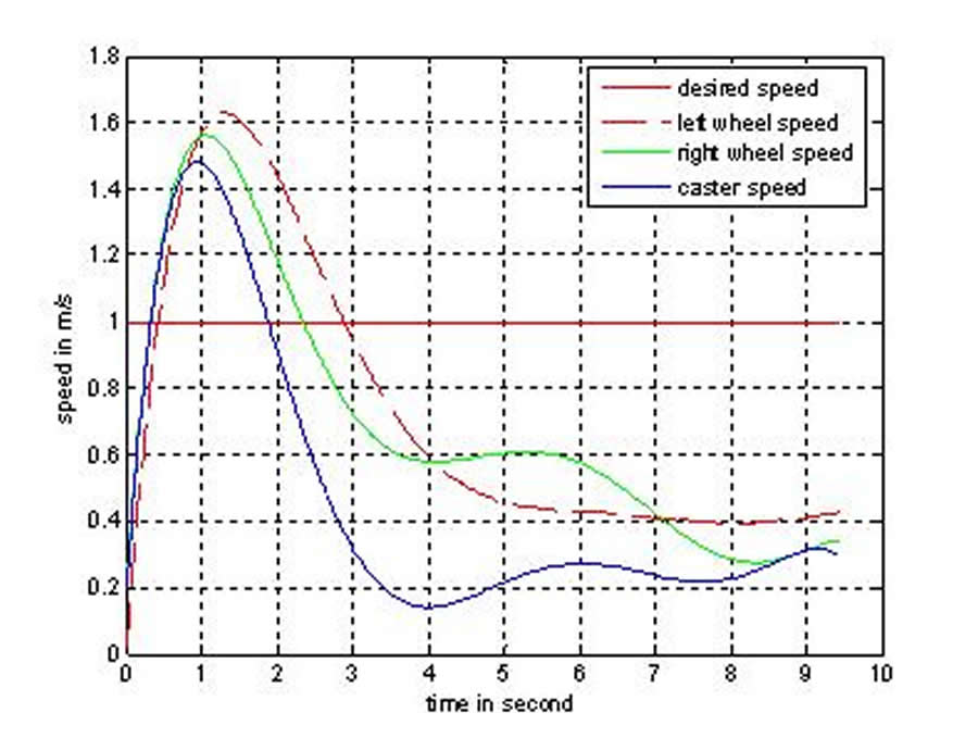
Figure 6. (Click for larger view)
The data collected indicate that the anti-slip controller successfully detected slip and significantly decreased the slip coefficient over all test conditions (terrain and speeds). The results also showed that the performance of slip-detection and traction control was consistent over different surfaces and speeds. With open loop control, the faster the speed the larger the slip coefficient indicates greater reduction in traction. However, with anti-slip control, the slip coefficient was similar at different speeds because when slip exceeded the pre-defined threshold the algorithm decreased the driving wheel speed to increasing the traction. There was no obvious change of slip coefficient on the five surfaces as there was with different speeds. The possible reason for this is that we did not visibly see the slip of the wheelchair.
This control system test experiment could be improved in several ways. The driving program needs to incorporate feedback from the inertia sensor on the wheelchair base to more accurately detect the slip and in act control of traction. The results obtained may be only valid for the current EPW setup and user so further tests will be necessary to generalize the results. More terrain types should be tested such as different types of carpets, wet surfaces, cross-slopes, and additional ramps. Further investigation is needed to develop more effective and rapid means of implementing anti-slip control.
REFERENCE
- Tadano, S. and Tsukada, A., “Some mechanical problems to use electric wheelchairs in a snowy region”, Human Biomechanics and Injury Prevention, pp. 199-204, 2000.
- D. Ding, and R.A. Cooper, “A review of the current state of electric powered wheelchairs.” IEEE Control Systems Magazine, vol. 25 no. 2, pp. 22-34, 2005
- Makki, A. and Siy, P., A robust traction controller design using the theory of variable structure systems, Proceedings of the 36th Midwest Symposium on Circuits and Systems, 1993, 356-359.
- Tan, H. S. and Tomizuka, M., Discrete-time controller design for robust vehicle traction, IEEE Control Systems Magazine, 1990, 107-113.
- Cooper, R.A. “Intelligent Control of Power Wheelchairs,” IEEE Engineering in Medicine & Biology Magazine, vol. 14, No. 4, Jul./Aug. 1995, pp. 423-430, New York, U.S
- Salatin B.; Grindle G.G.; Wang H.; Cooper R.A., “ The Design of a Smart Controller for Electric Powered Wheelchairs”, Proceedings of the IASTED International Conference on Assistive Technologies, pp. 133-138, Baltimore, MD, April 16-18, 2008
- Ward, C.C., Iagnemma, K., “Model-based wheel slip detection for outdoor mobile robots,” 2007 IEEE International Conference on Robotics and Automation, pp. 2724-2729, April 10-14, 2007
ACKNOWLEDGEMENT
This work was supported in part by the National Institutes of Health (1R03HD048465-01A1), Quality of Life Technology Engineering Research Center, National Science Foundation (EEC-0540865), and the VA Rehabilitation Research and Development Service (B3142C).
Author Contact Information:
Hongwu Wang, Human Engineering Research Labs, VA Pittsburgh Healthcare System, Pittsburgh, PA 15206; Phone: (412) 954-5322 Fax: (412) 954-5340, Email:how11@pitt.edu